Recall that a controlled source is one whose output voltage or current is determined by the magnitude of another, independent voltage or current. We have used controlled sources ex~ensively in our study of transistor-circuit models, but those were, in a sense, fictitious devices that served mainly to simplify the circuit analysis. We wish now to explore various techniques that can be used to construct controlled voltage and current sources using operational amplifiers. As we shall see, some of these sources are realized simply by studying already-familiar circuits from a different viewpoint
Voltage-Controlled Voltage Sources
An ideal. voltage-controlled voltage source (YCYS) is one whose output voltage V” (I) equals a fixed constant (k) times the value of another, controlling voltage: Vo = kV,; and (2) is independent of the current drawn from it Notice that the constant k is dimensionless. Both the inverting and non inverting configurations of an ideal operational amplifier meet the two criteria. In each case, the output voltage equals a fixed constant (the closed-loop gain, determined by external resistors) times an input voltage. Also, since the output resistance is (ideally ) 0, there is no voltage division at the output and the voltage is independent of load. We have studied these configurations in detail, so we will be content for now with the observation that they do belong to the category of voltage-controlled voltage sources.
Voltage-Controlled Current,Sources
An ideal, voltage-controlled current source is one that supplies a current whose magnitude (I) equals a fixed constant (k) times the value of an independent. controlling voltage: I” = k Vi; and (2) is independent of the load to which the current is supplied. Notice that the constant k has the dimensions of conductance (siemens). Since it relates output current to input voltage, it is called the transconductance, gill, of the source.
Two familiar amplifier circuits: the inverting and non inverting configurations of an operational amplifier. Note, however, that we now regard the feedback resistors as load resistors and designate each by RL• We will show that each circuit behaves as a voltage-controlled current source, where the load current is the current l.. in RI,.
In Figure 14-IO(a). v h virtual ground. so I, = V”,I!?,. Since no current flows into the inverting terminal of the ideal amplifier, II = I,. or Equation 14-2-l shows that the load current i:the constant 1/R, times the controlling voltage V”,. Thus. the transconductance is gill = 1/R, siemens. !VII’:: tl:«t UI. doc» not appear ill the equation, so the load current is imlrpcndcnt (,1′ .oad Iesistance. Like any constant-current source, the load voltage (voltage across .’?r) will change if RI is changed, but the current remains t te same. Tbe direction of the current through the load is controlled by the polarity of V”,. This version of a controlled . current source is said to have a floating load, because neither side of RI. can be grounded. Thus, it is useful only in applications where the load is not required to have the same ground reference as the controlling voltage, ViII’ In Figure 14-10(b). u: = ViII, so II = Vill/RI’ Once again, no current flows into the inverting terminal, so II. = I,. Therefore,
As in the inverting configuration, the load current is independent of RI and the transconductance is 1/R, siemens. The load is also f1oatin~ in this version. Of course. there is a practical limit on the range of lo:~d resistance RI that can he used in each circuit. If HI is made tuo I. rgc. the output oltugc of the amplifier will approach its maximum limit. as determined hy th·; pm cr supply voltages. For successful operation, the load resistance in each circuit must obey
Design an inverting, voltage-controlled current source that will supply a constant \ current of 0.2 mA when the controlling voltage is 1 V. What is the maximum load I resistance for this supply if the maximum amplifier output voltage is :20 V?
This equati n shows that the load current equals the constant (1 + R2/R,) times the controlling current and that h is independent of RL For successful oncraton. RL must obey
Note that the circuit of Figure 14-15 may be regarded as a current amplifier,the amplification factor being
The next example demonstrates the utility of current amplification and illustrates an application where a floating load may be used
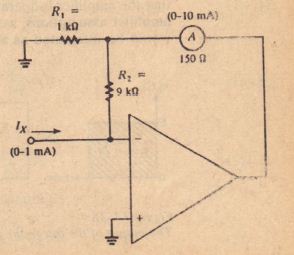
It is desired to measure a de current that r nges from 0 to 1 mA using an cr whose most sensitive range is 0 to 10m . To improve the measurement ai the current to be measured should be amplified by a factor of 10.
1. Design the circuit.
2. Assuming that the meter resistance is 150 nand the maximum output voltage of the amplifier is 15 V, verify that the: cir uit will perform properly.
Solution
1. Figure 14-17 shows the required circuit. l» is the current to be measured, and the ammeter serves as the load through which the amplified current Itows, From equation 14-39, the current a-nplification is lill» = 1 + R21R1 = 10. Letting R, = 1 kfl, we find R2 = (10 – 1)1 kO = 9 kf
2. Inequality 14-38 must he satisfied (or the smallest possible value of the righthand side, whieh occurs when lin = 1 mA:


